home
needs
local resources
comfort
safety & health
contact
reports
Flow through stove
Flow patterns in a stove, together with local velocity profiles, are mainly determined by the flow resistances inside the stove. The driving force for the flow is the draft resulting from the temperature differences between the gases in the stove and the ambient air. In this section we shall be using three generic designs for which a reasonable amount of experimental evidence is available that demonstrate the importance of the concepts discussed in this sections to obtain a desirable performance of the stove.The designs are:
- (i)
- the shielded fire which is a chimneyless single pan stove (fig. 1a);
- (ii)
- the so-called Tamilnadu stove which is a large stove meant for preparing food in hostels and schools and is essentially a chimney version of the shielded fire (fig. 1b); and
- (iii)
- the ASTRA stove which is a multi-pan mud stove with a chimney (fig. 1c).
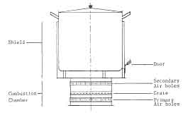
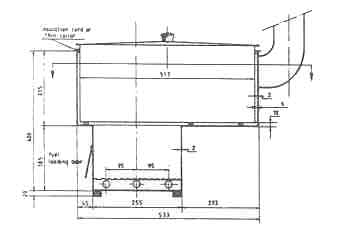
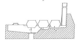
Fig.1. Stove Designs (a). The Shielded Fire (b). The Tamilnadu Stove (c). The ASTRA Stove
Flow Resistance
Understanding the pressure distribution in the stove is important for stove design and development. It plays an important role in the decisions about locating the combustion air holes, control mechanisms, and the heat transfer surface, i.e., the pans. Unfortunately, the stove geometries are such that pressure drops over the stove cannot be calculated with reasonable accuracy. The available formulas, most of them from mechanical engineering practice, are only valid for simple geometries . An extra complicating factor is the temperature change of the gases passing through the stove. Verhaart (1981) has collected information to calculate draft and flow resistance. Pressure loss factors are presented for straight channels of constant cross section, bends, sudden enlargements of passage, and sudden reduction of passage . Channels with a noncircular cross section are related to the circular cross section by means of the hydraulic diameter of those channels. Verhaart (1981) gives an example calculation for a stove called Pogbi stove, but the results of the calculation were never checked against experiments.
One can think of many more stove components or geometries that introduce a
pressure drop in a stove, for instance grate, fuel bed, air holes, dampers,
annulus-like spaces around pans, etc. For most of these cases no readily
applicable formulas are available in the literature. Sometimes the geometry
is in accordance with the literature, but the flow conditions differ. For
instance, the VDI-Warmeatlas (1977) gives a chapter on ``Druckverlust bei
der Strömung durch Schüttungen.'' One could think of using this theory
to calculate the flow resistance of the fuel bed. But in a fire the fuel bed
is also a reaction zone, which introduces a number of extra problems. So one
would have to adapt this theory to the particular situation. Until now this
has not been done. Another example can be given of a situation where theory
is directly applicable to stove practice. The pressure drop over a hole in a
flat metal plate can be calculated using a contraction model presented by
Becker (1968). Pressure drop is characterized by a contraction factor. For
the case of the combustion air entrance holes of the shielded fire,
application of the theory gives a value for the contraction factor
![]() = 0.61, whereas experiments on the stove give
= 0.61, whereas experiments on the stove give
![]() = 0.69. For the present state of the art of stove designing, this result can be considered
to be good. In fact Kumar et al (1990) demonstrate for the ASTRA stove that
the reduction of the area of air entrance from 120 to 24 cm2
results in an increase in the overall efficiency from 16 to 24%. In other
words reduction in air supply can be achieved by introducing an appropriate
resistance in the flow circuit - in this particular design the inlet area
for flow has been chosen for introducing the resistance. The increase in
efficiency is attributed to a reduction in excess air leading to a higher
combustion temperature whose beneficial effect on efficiency has been
demonstrated elsewhere . We shall consider other examples as we proceed
with the discussion in this and the next section.
= 0.69. For the present state of the art of stove designing, this result can be considered
to be good. In fact Kumar et al (1990) demonstrate for the ASTRA stove that
the reduction of the area of air entrance from 120 to 24 cm2
results in an increase in the overall efficiency from 16 to 24%. In other
words reduction in air supply can be achieved by introducing an appropriate
resistance in the flow circuit - in this particular design the inlet area
for flow has been chosen for introducing the resistance. The increase in
efficiency is attributed to a reduction in excess air leading to a higher
combustion temperature whose beneficial effect on efficiency has been
demonstrated elsewhere . We shall consider other examples as we proceed
with the discussion in this and the next section.
Although the available theories on flow resistances cannot always predict the actual pressure drop, they can assist in showing trends, orders of magnitudes, or the sensitivity of a particular stove concept to certain changes with regard to pressure loss. We will give a couple of examples of this type of calculation (Bussmann, 1983). These examples concern the shielded fire, which is a stove that is composed of simple geometric shapes and is therefore more amenable for pressure-drop calculation models.
The annular space between pan and shield is an important part of the shielded fire. It is the major zone for convective heat transfer to the pan and the design tries to increase this heat transfer by increasing the flue gas velocity (the heat transfer aspects will be considered in section 6.3). Therefore, the gap must be made as small as possible, with an increasing flow resistance as a consequence. Figure 2 shows this flow resistance as function of the gap width calculated according to the formulas given by Shah and London (1978). The parameters for the different curves are the volume flow of the flue gases and the flue gas temperature.
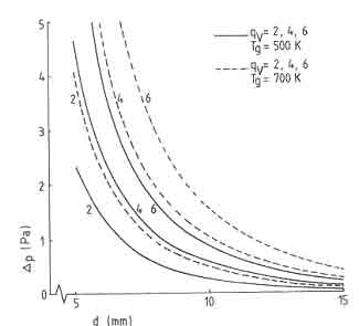
Fig.2. over an annular gap for different flows and gas temperatures
The figure clearly shows that for gap widths of less than 10mm the flow resistance of the annulus becomes a very decisive part of the total flow resistance of the stove, considering that in this case the maximum available draft is about 3 Pa. Again, these calculated values are not verified by experiment, but the trend is very clear and will also appear in practice. This trend shows a very important fact: optimization of the gap width should match the accuracy of the production system. At a design value of 10mm for the gap width, a deviation of 1mm from that value will not be disastrous. At a design value of 6mm, a deviation of 1mm can be the cause for the stove not working at all!
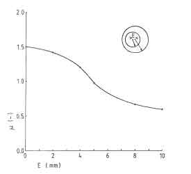
Fig.3. eccentricity on flow resistance in an annulus
The eccentricity of the pan in the shield has a distinct influence on the flow resistance, as is shown in Figure 3 This gives the flow resistance factor versus eccentricity; the formulas for the calculations are taken from VDI-Warmeatlas. From the figure it can be seen that the flow resistance reduces 35% when the pan center is 5mm out of the stove center. Obviously the biggest part of the flue gases will pass through the biggest passage, reducing the heat transfer to the opposite side of the pan.
Finally, Figure 4 gives the equilibrium situation of flow resistance in the annulus and the air entrance holes for two types of shielded fires when the total available draft is 2.48 Pa. From the figure it is clear that there is little room for varying the gap width. Only a reduction to 7 mm is possible, otherwise the necessary diameter for the air entrance holes becomes unrealistically large.
A discussion on flow resistance cannot end without a word on control. There are basically two ways of controlling the power of a stove, via fuel supply or via air/gas flow. Controlling the air or gas flow through the stove is done by manipulating the resistance to flow at a certain spot in the flow channel. Normally, the choice is made for control of combustion air or control of flue gases at the bottom of the chimney.
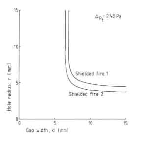
Fig.4. Available draft over the main flow resistances
Of the flow control methods, control of combustion air is to be preferred (Verhaart 1983). The available pressure drop for the controlling action should be such that a real control is possible. This can be illustrated again for a shielded fire. Looking at Fig.1, for a shielded fire with a gap width of 10 mm and an assumed total draft of 2.5 Pa, at a flue gas temperature of 700K, a volume flow of more than 6 litres/sec will flow through the stove. Introduction of a resistance of the order of 2 Pa for purposes of control will reduce the flow down to 2 liters/sec. If a pressure drop of 1 Pa is assumed over the other parts of the stove (grate, fuel bed, bends), then for d = 10 mm this is still possible. But for a gap width of 8 mm, under the above circumstances a volume flow of 4 litres/sec is impossible. So the controlling action can only influence the flow through the stove in a very limited way, because the main governing resistance is confined to the annulus. Here lies the reason that for many stoves provided with a damper, the controlling effect of this damper is only noticed at the very end of the closing movement. Then the introduced resistance becomes important in relation to the built-in flow resistances in these stoves.
Thus, in stove designing, flow resistance calculations should be made or at least obtain the best possible estimates to be able to limit power and gas flow to desired proportions and to provide effective flow control.
Many of the ideas described above will be used in the section on design to demonstrate the usefulness of calculating the flow resistances in a stove to achieve desired design objectives.
Flow Patterns
Whereas the draft and friction determine flow through a stove in an overall sense, local flow resistance determines the flow patterns in a stove. The influence of different flow patterns on the performance of a stove can be substantial. To calculate these influences is an extremely complex task and one has to rely on experiments. Unfortunately only few systematic experiments have been done for geometries that are of interest to stove designs. Before presenting them (which are not necessarily typical) it is useful to become aware of a qualitative picture of the different possible effects (Krishna Prasad 1981).
We first consider the prototypical two-pan clay stove that seems very popular in stove development circles. The basic theory underlying such stoves is the principle of heat recovery from hot gases leaving the stove. Figure 5 shows a cross section through such a stove. Locally, the flow is governed by the buoyancy and the draft from the chimney. We consider two extreme cases in order to gain an appreciation of the role of the chimney.
- (i)
- When the buoyancy is very much larger than the draft: a situation obtained with a very large fire coupled with a very short chimney.
- (ii)
- When the buoyancy is very much smaller than the draft: a situation obtained with a small fire and a tall chimney.
In the first case smoke and maybe flames will leak past the first pan. The second pan receives little heat. The design is thus counterproductive. The gas path is shown in Fig.5a. In the second case the combustion gases are swept away from the first pan and will come into contact with a small portion of the second pan. Thus the first pan will receive only the radiant heat from the fuel bed. The second pan will receive a little convective and a very small amount of radiant heat. Next, since the gases deliver a relatively small amount of their heat to the pans, their temperature at the chimney base will be quite high, thus making an already poor situation worse.
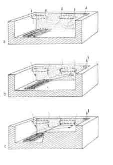
Fig.5. patterns in a two-pan stove with some arrangements for flow control
5 Because of the rather large draft, there will be considerable cold air leaks past the pans into the enclosure. This will produce lower temperatures under the second pan thus reducing further its heat input. This to a certain extent counteracts the effect of high temperature at the chimney. The gas flow path for this case is shown in Fig.5b.
Quantitative results pertaining to the last effect mentioned above were obtained by Lokras et al. (1990) on the ASTRA stove. The results were obtained on a configuration that is slightly different from the one shown in Fig.1c and is indicated in Fig.6 An intentional hole with an area of 1.5 cm 2 was provided between the second and third pans and near the surface of the third pan. There was no change in the efficiency of the first pan, a drop from 10.8 to 9.7% in the second pan while the third pan efficiency dropped from 4.6 to 1.7 which is over 63% drop. In this configuration the total efficiency drops from 33 to 28.9% which cannot be considered very significant.

Fig. 6. For testing the effect of leaks past pan III on the stove efficiency
6 However for a two-pan stove with illfitting pans this can be an enormous effect and thus a chimney stove has always to be operated with correct pan sizes or needs to incorporate special features such as collars to provide proper fitting between the pan and the pan hole. Needless to say the design complexity along with the cost will increase considerably.
The ideal situation is one where the chimney height is so adjusted to equalize buoyancy and draft just under the first pan. Under such circumstances, the fire will rise up to the first pan where it will veer to the right under the influence of draft. This is known as the balanced draught operation in boiler practice. However, for a small device such as a wood burning stove, it is doubtful whether such a fine tuning of the two forces can be realized. Moreover, the system can prove unstable and oscillate between two undesirable conditions due to variability of combustion characteristics and uncertainty of fuel quality.
In general, it appears preferable to operate with the draft slightly dominating the buoyancy. In such a case the first pan will receive less heat input than in a well-shielded open fire operated under optimum conditions. There is some experimental evidence in support of this claim (Nievergeld et al. 1981, Visser and Verhaart 1980).
A fruitful approach for improving convective heat transfer is the introduction of baffle. It is a vital element of any stove that has a chimney and incorporates two or more pans. Even for a design with a single pan a chimney will perform poorly (see Salariya 1978 for an example). Some comments on such designs will follow later in the section. Figure 5c shows the form of the baffle. The most important effect the baffle will have is that the burned gases are forced to move up toward pan 1 (irrespective of the relative values of buoyancy and draft) before turning right in the direction of the chimney.
The first pan will receive considerable convective heat transfer, which was virtually absent in Fig.5a. A second advantage is that the baffle defines the combustion volume better. In particular, the fire surrounded by insulating hot walls except for the fuel loading door and the gap between the baffle and the top of the stove. The ``cold'' pan is quite ``far off'' (provided height for combustion is adequate). Thus the conditions for complete combustion of the volatiles are much better.
Furthermore, the second pan will receive much more convective heat, as can be seen by comparing Fig.5b and c. The weakest link in the closed stove is the convective heat transfer. A baffle is a must to provide adequate area of contact between the pan and the hot gases. In order to determine this the gas motion trajectory needs to charted. It depends on the buoyancy and draft (already discussed), the shape of the baffle, the location of the chimney vis a vis the fuel bed, and in some cases the chimney diameter.
Figure 7 shows the most probable path of the gas motion for the design of Fig.5a. Several interesting features emerge from a study of the figure. The first point is the width of the gas flow path. Under the first pan it is essentially controlled by the width of the fire. For this design it is equal to the length of the wood actually burning in the combustion chamber. Second, during the entire trajectory the gas is subjected to an accelerating flow field; the chimney diameter is only 70 mm, and it is located on the top right-hand corner of the stove. So much of the actual width of the gas motion goes on decreasing as it reaches the chimney. Third, some part on the left-hand side of pan 1 is completely missed by the hot gas. This missed region is reduced in this design by setting the firing place somewhat to the left of the first pan. A modified design suggested by Micuta (1981) is shown in Fig. 8.
It has an in-line arrangement in which the fuel loading door, the pans, and the chimney are all located along a single axis.
Fig.7. Most probable path of gas motion in a two-pan stove
Figure 8a shows that the baffle wall facing the fire is much steeper than the one in Fig.5c and can be expected to provide much better conditions for combustion as well as radiation. The inlet to the chimney is located at the bottom of the stove rather than at the top as in the previous case. The chimney diameter is larger. Both these factors assist in maintaining a larger area of contact between the hot gases and pan 2. The expected contact areas are shown in Fig.10b. As compared to the previous design, the first pan fares worse in this case primarily because the previous design had its fuel loading door centerline offset to the left of the centerline of pan1.
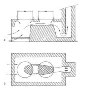
Fig.8. Flow Patterns in a stove with an in-line arrangement and baffle
The most significant gain in heat transfer area is observed for pan 2. The chimney height is larger and so is its diameter. The exact effect of this on flow paths is difficult to estimate and requires careful experimentation. On balance one should expect a better performance from this design. One could think of yet another alternative for the baffle (see Fig. 9), with the rest of the design left intact.
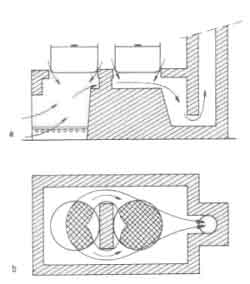
Fig.9. Flow pattern in a stove with an in-line arrangement, a baffle and a flow obstruction
6 The heat transfer areas for both pans are increased (the extent of this increase can only be determined by experiment). Probably the best arrangement might be to retain the firing-door arrangement of Fig.5. A word of caution here. Unless the resistances to flow in the two passages of Fig.6.13 are matched carefully, there is the danger of the flow completely missing one of the passages.
Again we turn to the work on the ASTRA stove to provide a quantitative result on the effects described above. Fig.10 is really a configuration of the stove with a baffle in the form of a diffuser between the second and third pans. The shaded regions at the bottom of the stove are the soot marks. In the absence of the baffle the flow pattern will look like the one shown in fig.6.14. Clearly the contact area for the third pan is drastically reduced.

Fig.10. Patterns of soot marks on the stove bottom in the absence of a baffle 6.14
There is a slight drop in the first pan efficiency from 18.2 to 17.9second and third pans change from 9.9 and 2.9 to 12.3 and 4.4Again this appears a small change; for a two-pan stove the change can be substantial.
We have some experimental data on a two-pan heavy stove tested at TNO in the Netherlands to substantiate the last claim. Van der Heeden et al. (1983) carried out a series of tests on the Nouna stove, a design originating from Burkina Faso in West Africa. The original design and the three modifications to it are shown schematically in Fig.6.15. Some of the principal dimensions of the stove modification ``C'' are shown in Fig.6.16. The extent of improvement recorded for each of the successive modifications is shown in Fig.6.17. All these results were obtained at a constant power of the fire of 8.5 kW and damper being 25% closed. While the first pan shows a modest increase in efficiency, it is the second pan that registers dramatic increases in efficiency. The rather high efficiency of the modification ``C'' has been achieved not only through the introduction of the baffle but also by using a larger pan - a pan of the same size as the first pan. This design feature has a lot to commend it since many a multi-pan stove is recommended to be used by interchanging of pans so that heat demand variations during different cooking phases could be accommodated.
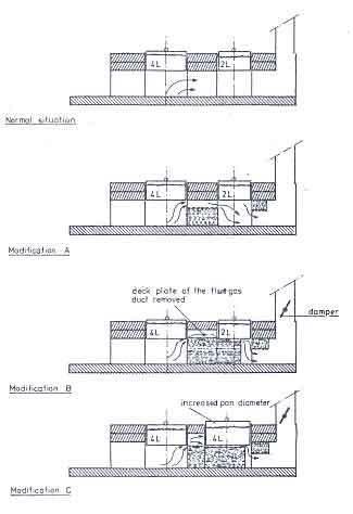
Fig.11. The Nouna Stove and modifications 6.15
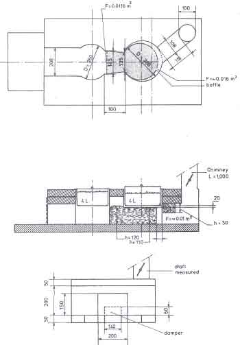
Fig.12. Principal dimensions of the Nouna stove (modification ``C'') 6.16
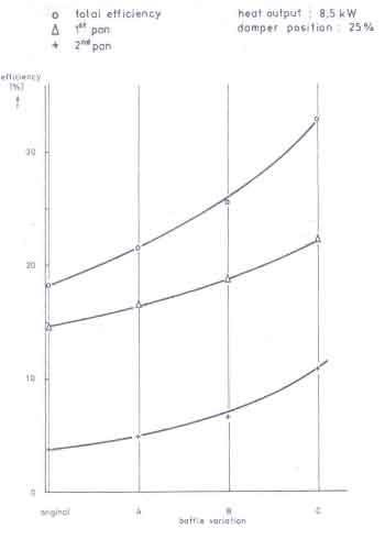
Fig.13. Efficiency Improvements with modifications 6.17
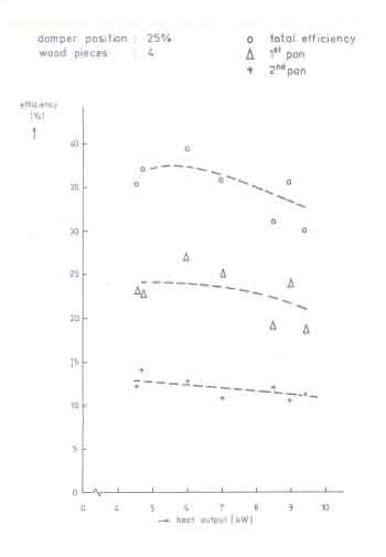
Fig.14. Efficiency as a function of power level of the fire for Nouna ``C'' stove
This not only confirms the open fire finding that efficiency is not a very strong function of power of the fire, but the influence of the baffle is not also strongly dependent on the power of the fire. It shows that a total efficiency of the order of 37.5% could be obtained in contrast to 17.6% of the original design at a power level of about 6 kW (Claus et al. 1981).
A remarkable feature emerges from a study of the contact areas in different arrangements for convective heat transfer. Unlike the open fire it appears advantageous for these designs to maintain the fire diameter nearly equal to the pan diameter for promoting convective heat transfer to the pans. This is of course subject to the power level of the fire, which is controlled by the base diameter of the fire.
This discussion clearly points out the inherent difficulties involved in designing such stoves to realize their full potential. Some of the benefits claimed for such stoves are doubtful and more work on them should await more definitive information on the use to which second pan could be put to. In the rest of this section we shall be considering only single-pan stoves.
In a shielded fire (Fig.1), effects on the flow patterns similar to the ones described above can be observed. Figure 15a shows a closed version of the shielded fire.
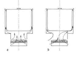
Fig.15. A function of power level of the fire for Nouna stove.
Because of the axisymmetric arrangements of the air entrance holes the combustion gases nearly divide themselves around the pan. Once a door is opened, as is necessary to burn long wood, the situation changes dramatically, as illustrated in Fig.15b. Cold air is entrained and pushes aside the combustion gases from the front portion of the pan, thus reducing convective heat transfer. The best way to overcome this problem is to keep the door closed and use short wood. The second best is to reduce the gap width so that, due to increased flow resistance, less cold air is drawn into the stove. But this solution demands very accurate production, as discussed in the previous section. The last possibility is to place pan and/or combustion chamber eccentrically. This will force the entrained air to divide evenly around the pan and partially pass through the fire, thus making the situation better. Once a chimney is added to a shielded fire (fig1b)>, the problems that arise are similar to the ones discussed with the two-pan clay stove: the combustion gases tend to follow the shortest way to the chimney. So even if the stove is properly designed so that no excessive amount of cold air is sucked inside, the convective heat transfer can be poor because the gas flow around the pan is badly distributed (see Fig.16a). Here eccentricity of pan and/or combustion chamber can improve the gas distribution, or a baffle in the shape of an eccentric ring can be introduced, to adjust local flow resistances so that the desire flow pattern is established (Fig.16b). The situation of Fig.16b has been studied in some detail by Bussmann (1988) and de Kruijf (1987). In order to establish the flow patterns they measured the pressure distribution around the pan with an experimental arrangement shown in Fig. 16.
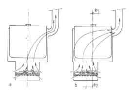
Fig.16. in a shielded fire with a chimney with the combustion chamber placed along
the axis of the pan and eccentrically set-up for pressure measurements
Air at ambient temperature was blown through the stove and the pressure difference with respect to a reference point at the stove's air inlet was recorded with a pressure sensor. The air flow was kept constant during the experiments and a calibrated orifice meter was used to metre the flow. The pressure was recorded at 18 locations along the circumference of the pan at two heights from the combustion chamber top: 0.1 to 0.9 at a height of 10mm and 1.1 to 1.9 at a height of 90mm. Figure 17 shows the location of these pressure taps.
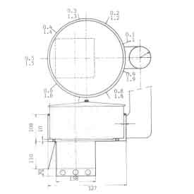
Fig.17. The pressure tap locations
Experiments were performed by varying the total flow through the stove and the gap widths between the pan and top plate. The results are shown in Fig.18 as a function of position around the pan. The data points are all pressure differences with respect to the reference point. The pressure drop increases towards the chimney entrance (sample points 1 and 9). The minimum is found around the combustion chamber door. Increasing the flow and decreasing pan bottom gap have similar effects on the pressure drops. This is not a surprising result if we note the increasing the gap width reduces the resistance to flow with a consequent increase in the flow through the stove. However it is not easy from these figures to determine whether there is a short-circuiting effect.
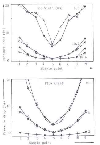
Fig.18. Pressure distribution around the pan
(a) for different flows though the stove
(b) for different gap widths between pan and the top plate
This effect can be seen by plotting the data set after normalization of pressures according to
These plots are shown in Fig.19. Fig.19a shows that varying the flow rates does not affect the value of P*. But the gap width has a substantial effect on P* ; at the measuring station 8 for example changes P* from about 0.25 to about 0.75 when the gap width is reduced from 16.4 to 6.4. Low pressure drop implies low resistance to flow implying that the flow is making a bee line to the chimney - a high short-circuiting effect. One could derive the information also by looking at the soot marks on a clean pan. This could be supplemented by standard efficiency measurements, as was done for the ASTRA stove. However pressure measurements provide a useful tool to derive the proper dimensioning of the stove flow path. For this case a gap width of 10mm seems to be a good compromise between the minimization of short circuiting effect and maximizing the production possibilities.
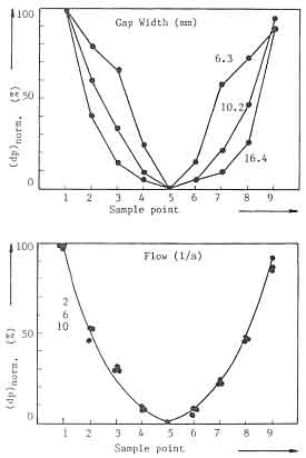
Fig.19. Dimensionless pressure distribution around the pan
(a) for different flows though the stove
(b) for different gap widths between pan and the top plate
The discussion in this section clearly illustrates difficulties one encounters in designing a stove for high efficiency. Much work - primarily of an experimental type - needs to be done before one can come up with workable designs.